This tutorial is meant to complement the first lecture of the course High Energy Astrophysics. Here you can practice your knowledge of the topic after completing Lecture 1.
Sometimes you will find some collapsable/expandable paragraphs marked in blue (questions) or orange (quizzes). These are quick tests to check your knowledge as you follow the tutorial. Click on the paragraph to read the answer.
Radiative Transfer Theory Basics
Radiative Transfer Approximation
Electromagnetic radiation is described by the Maxwell equations. Energy is transported by a transverse wave in the electric and magnetic fields. The Maxwell equations need to be solved in order to find how these waves interact and propagate. When photons propagate through macroscopic media, the solutions of the Maxwell equations become too complex to solve for all practical purposes. There are two simplifications that can be done without losing generality:
- The first is that of geometric optics, with photons approximated as light rays. Here the scale of a system
 greatly exceeds the wavelength of radiation : . The wave nature of photons is considered only to the extent that it introduces light bending on surfaces and changing of refraction index.
 - If the index of refraction is everywhere (or at least it can be safely approximated as everywhere), then we talk about radiative transfer, which represents a further simplification with respect to geometric optics.
 greatly exceeds the wavelength of radiation
  :
:  . The wave nature of photons is considered only to the extent that it introduces light bending on surfaces and changing of refraction index.
 everywhere (or at least it can be safely approximated as
 Specific Intensity Definition
Exercise 1
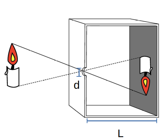
Let’s consider a pinhole camera, which is nothing but a small hole in a box, able to generate an image without using a lens. Let’s assume that the hole is circular with a diameter  . Let’s say that the box has a depth L so that the rays have to cross a distance
  before reaching the image plane. If a source of light with a specific intensity (sometimes also called surface brightness)
  is placed at a certain distance from the pinhole, then we can calculate what specific flux
  is received at the image plane.
What is the meaning of “specific” in the specific intensity and flux?
Specific means that the quantity is calculated per unity frequency. That’s why you see  at the bottom of and , i.e., they are functions of .
In this exercise, we want to calculate the flux as a function of  . Here
  represents the angle in the x-y plane between the source and the pinhole, whereas
  is the azimuthal angle. We want to show that:
![\[ F_\nu = \frac{\pi\,cos^4\theta}{4\,f^2}I_\nu(\theta, \phi)\]](https://blacksidus.com/wp-content/ql-cache/quicklatex.com-7e0d6d6e1b4d2f10a80d22761a14ac59_l3.png "Rendered by QuickLaTeX.com")
where  is the focal length.
Solution 1
Before reading the full solution, consider the following hints.
Hint 1
Start with the general relation between specific flux and specific intensity and consider that, given that , the specific intensity can be considered constant across the circular aperture.
Hint 2
Remember the definition of solid angle:  . Here
  and
and  is the normal unit vector so that
  . Consider also that the values are constant for all variations of , so you have to integrate only the area of the pinhole.
Solution
The relation between specific flux and intensity is  . Since we consider the angle as to varying over the tiny area of the pinhole, we have
  .
.
The solid angle is . The  can be again brought outside the integration.
The pinhole area is then  . Putting all together we have:
Exercise 2
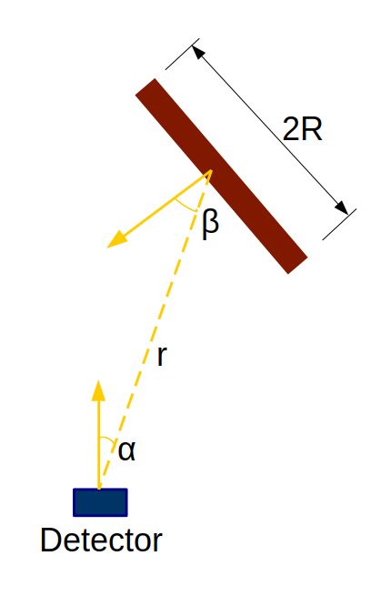
A thin disk of material is emitting radiation with specific intensity . The disk is “thin” in the sense that its height  , where
  is the disk radius. The radiation emitted is collected by a detector placed at a distance
  . The angle between the line of sight and the direction normal to the disk is
  , whereas the disk is seen at an angle
  . Calculate the flux measured by the detector. The solution should be a function of both and .
Solution 2
As usual, let’s start with some hints.
Hint 1
Start by using the usual expression relating the specific flux and specific intensity:  .
.
Hint 2
Consider the angle . Since , will it vary much when integrating the specific intensity over the solid angle?
Hint 3
Remember the expression for the solid angle  , where
  .
.
Solution
Let’s start with . Since will be nearly constant, we can take it out of the integral. Therefore  . Since
  , we have that
  . Putting it all together above we have
  .
.
The Constancy of Intensity in Free Space
If the rays propagate in free space, then the (specific) intensity does not change with distance. This might sound counter-intuitive at first. Indeed we know very well that the inverse square law tells us that, in free space, the flux of an object decreases as the square of the distance. So why do we say that the surface intensity remains constant? The keyword here is surface, meaning that we are observing an extended object and not a point source. Remember that the apparent size of an extended object, i.e., its solid angle, decreases with the square of the distance so that you squeeze more and more surface elements into a given solid angle. So the “number” of surface elements emitting light in the field of view increases as the square of the distance, whereas the flux we receive decreases by the square of the distance. The two effects cancel each other out and we have a constant surface intensity.
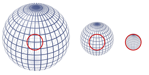
In the image on the left, the spheres represent an extended object emitting light at distances  , 2, and 4. The circle is the detector (e.g., eye, telescope, camera, etc.) with a fixed size. As the distance increases the surface area of the sphere scales as
  . However, more surface elements fall within the same solid angle, thus preserving the surface intensity.
Surface Intensity and the Moon
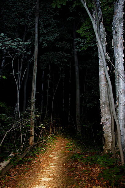
It might be worth insisting on this point a bit further with an even simpler example. Imagine walking in the countryside and looking at a row of nearly identical trees in perspective, like in the figure below.

Suppose you are close to the first tree, about 5 meters away, whereas the last tree you see is at about 500 meters. Since the flux scales as , you receive about 10,000 fewer photons from the last tree than from the first tree. However, you use the same exposure time to record the optimal picture, be it with a camera or with your eyes. You don’t see the trees fading away with distance!
This happens because all trees are roughly illuminated in the same way, so they all have the same surface brightness. Their flux decreases as , but so does their solid angle and the two effects cancel out.
Look at the picture in the panel below. The trees here are illuminated by a flashlight. Their intensity clearly decreases with distance. Why?
Solution
The reason is that the illumination does not come from a source at infinity – that would provide a uniform illumination – but from a flashlight. Therefore the amount of light reaching each tree scales as and therefore the intensity is not the same for all trees.
Exercise 3
The specific intensity (or surface brightness) of an object remains constant in free space. Give now an expression that describes how the specific intensity changes when there is some absorbing material along the line of sight (to be clear: you need to write the radiative transfer equation when only absorption is present and solve the equation by giving an expression for  ). Call the absorption coefficient
  and the initial specific intensity as
  .
.
(NOTE: you can also choose to write and solve the transport equation in terms of the optical depth  rather than and
  ).
).
Do you remember the definition of the absorption coefficient?
Think in microscopic terms…
The absorption coefficient is a consequence of the interaction with microscopic particles with number density  and cross-section
  :
:  .
.
Now imagine having a box with absorbers. In the image below the cross-section of each absorber is represented by a small red circle. Select the correct picture below by answering the question.
Solution 3
Let’s start by writing the equation of transport for the absorption-only case. This means we will set the emission coefficient  to zero and ignore any scattering.
What are the dimensions of the absorption coefficient?
has units of  , so dimensions
  . Therefore
  is a dimensionless quantity.
The differential expression for the equation of transport is therefore  . Integrating this expression we get
  .
.
Source Function
In the previous exercise, we mentioned that you can use the optical depth in place of the absorption coefficient and the length  . Remember that the infinitesimal optical depth, for the case of absorption only, is defined as
  .
.
Can you write the transfer equation as a function of the optical depth?
Hint 1
Remember to add the emission coefficient , which has units of  .
.
Solution

The ratio between emission coefficient and absorption coefficient is called source function  and has the same dimensions of specific intensity. The source function works very well together with the optical depth, since it tells how the specific intensity varies along the optical depth scale.
The source function is not only a useful quantity to rewrite the equation of radiative transport in a simpler way, but it has also a profound physical meaning. The source function, having the dimensions of a specific intensity, can be thought of as the local input of radiation. For example when the optical depth  then
then  which means that matter far from the location of interest is giving a negligibly small contribution to the specific intensity. In other words, the source function is the value approached by the specific intensity given sufficient optical depth.
The Meaning of the Source Function
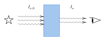
Let’s illustrate the meaning of the source function with an astrophysical example. An astrophysical source has intrinsic specific brightness  and emits a number of rays that cross a medium with optical depth . After the usual absorption and emission processes, the modified specific brightness reaches the observer that detects the photons with a receiver. For the medium, let’s choose the sky and approximate it as a uniform slab of gas whose optical thickness is
  , for example,
  at
at  GHz. Let’s assume that the specific intensity of the sky at 30 GHz is
  . From the equation of transport, what would be the specific brightness observed at 30 GHz with respect to the initial specific brightness ?
Hint 1
Use the equation of transport with the approximation of a constant source function  .
.
Solution
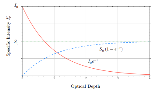
When is constant we can write  . Therefore the specific intensity
  . This is due to the absorption process plus a small contribution from the sky itself. The source function will be equal to the specific intensity corresponding to a specific emission process. For example, if the slab of gas is the Earth’s atmosphere, then, under the zero-th order approximation that it is in thermal equilibrium, the source function will represent blackbody emission, so that
  is the “background” contribution of the sky observed by the receiver. The radiation that emerges after crossing the slab of gas is therefore equal to the incident radiation attenuated by the optical depth plus the sum of each layer of the slab emission attenuated by the optical depth from that point to the receiver.
Leave a Reply